Simulation of plumes in infrared bands can reveal significant radiance information, depending on the operational state of vehicles, ships, or aircraft. For example, a plume can increase the size and/or signature of a target significantly. Imagine a plume rising vertically from the smokestack of a distant ship. The ship itself might have already dropped below the horizon (due to its distance from a low sensor position and the earth's curvature). However, the vertical extent of the plume might rise above the horizon, making the signature impact of the ship much more visible than if the plume was ignored.
Our MuSES software can effectively render exhaust plume radiance and related impingement effects to provide a complete first-principles ray-traced image, as perceived by the at-range sensor. From this, target contrast and other metrics of interest can be computed.
 Figure 1
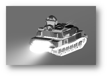
To accomplish plume radiance computations, MuSES needs a fluid volume mesh and a corresponding 3D distribution of temperature and species concentrations. These species include: C02, H20, and soot (carbon particulate). In practice, a Computational Fluid Dynamics (CFD) tool is used in conjunction with MuSES to predict the spatial distribution of pressure, temperature and species concentration. This plume data is then referenced when computing an infrared rendering of the target hardbody. Figure 1 shows a ZSU tank in motion with a plume rendered with MuSES in the MWIR band.
 Figure 2
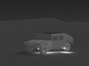
Plumes can also have secondary effects on the thermal solution. When exhaust gasses impinge on terrain or on the vehicle itself, the resulting surface heating can be incorporated into temperature and radiance predictions. The CFD flow field results can be imported twice, for different purposes (once for surface convection, and a second time for plume rendering). In Figure 2 the vehicle has been simulated as parked with the engine operating for several minutes with its exhaust impinging on the terrain, resulting in a “hot spot” on the ground. Note that no plume flow field is rendered in this image, to focus only on the terrain impingement effects.
 Figure 3
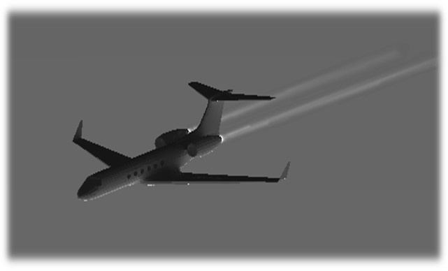
Once the hardbody temperature distribution and terrain/background are characterized, the rendering settings can be configured to include a plume. For transient scenarios, a series of renderings can be computed at different time steps, (and possibly with different plume files), to examine how a composite infrared signature would change over time. Figure 3 shows a twin jet engine aircraft with plumes rendered in MWIR. In such cases, the plume is likely to be the source of the most intense radiance, unless a view to the engine outlets is considered.
Rendering the scene begins by computing line-of-sight paths from each sensor pixel through the atmosphere toward the scene geometry. Each line-of-sight then intersects with either target, terrain or sky dome, and may pass through the plume volume. Contributions from temperature emissions, narrow band plume radiance and atmospheric effects are included. In this way, source radiance, plume radiance and atmospheric radiance/attenuation are fully accounted for.
The Plume Module is included with the standard MuSES license. However, if you do not have the resources available in-house for CFD analysis and plume prediction, our expert engineering team is available to help you with a service project. Please don't hesitate contact us!

