
Ensuring clear windshield and side window visibility in cold weather is a critical aspect of the vehicle development process. Traditional wind tunnel and cold chamber testing can be costly and time-intensive, making simulation a powerful alternative for validating defrost performance, as well as refining designs early in the development process.
In my recent webinar, I discussed how TAITherm enables engineers to accurately simulate the phase change process and validate defrost performance, while also ensuring compliance with safety regulations. The webinar also demonstrated how to integrate 1D HVAC models with 3D thermal/CFD simulations to assess the combined effects of airflow, glazing materials, and heating elements.
Windshield Defrost Performance Requirements
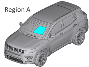
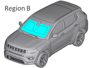
Windshield defrost performance requirements are defined by global regulations. In the US, these are found in the Federal Motor Vehicle Safety Standards (FMVSS) 103/104. The EU uses Economic Commission for Europe (ECE) regulation number 43.
These regulations divide the windshield into zones and specify percent melted targets within defined time limits. For example, EU standards require 80% of region A (driver's area) to be defrosted in 20 minutes and 95% of region B (the main windshield area) in 40 minutes.
 |
 |
Simulation Methods for Windshield Defrost
The automotive industry is increasingly adopting virtual verification and validation techniques to reduce development time and cost, and to enhance the design process. Simulation can be used to evaluate different windshield or HVAC designs early in the process, identify potential issues, and save time and money required down the road during physical testing.
There are several different simulation methods available, each with its own trade-offs between accuracy and computational speed. In this blog, we will compare the following methodologies:
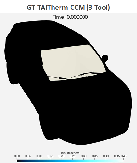
- GT-TAITherm-CFD Coupling: This three-tool coupling method is high-accuracy approach that couples GT SUITE, TAITherm, and a CFD tool to simulate the complex physics of defrost.
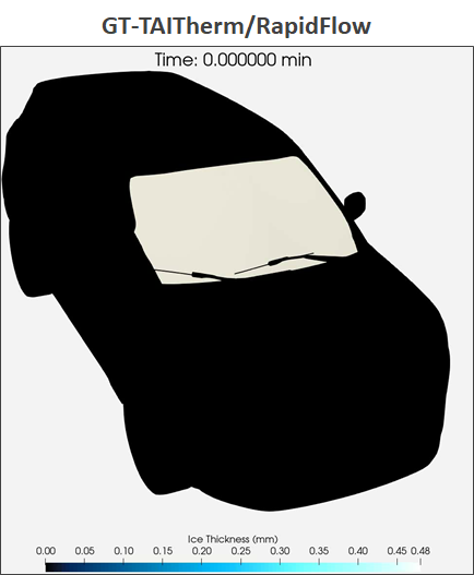
- GT-TAITherm/RapidFlow Coupling: This method uses a transient flow solver called RapidFlow, integrated into TAITherm, to enable fast transient thermal simulations.

Three-tool Coupling using GT-TAITherm-CFD
The three-tool coupling modeling approach utilizes a fully transient three-tool coupling between GT-Suite, TAITherm, and a CFD solver (Star CCM+ was used in this work) for detailed cabin climate and defrost analysis. GT-Suite models the HVAC system, providing transient vent flow rates and temperatures as boundary conditions to the Star CCM+ CFD model. Star CCM+ then simulates the 3D airflow within the cabin and exchanges convective and thermal boundary conditions with TAITherm. TAITherm, in turn, performs transient thermal analysis of the cabin and windshield, crucially incorporating a moisture transport model to simulate ice deposition and melting. This conjugate heat transfer solution accurately predicts local air and glass temperatures, as well as the ice melting process on the windshield, with validations showing accuracy within 2-3 degrees Celsius.

Two-tool Coupling using GT-TAITherm/RapidFlow
This section details a two-tool coupling simulation method employing GT-Suite and TAITherm/RapidFlow as a faster alternative to the GT-TAITherm-Star CCM+ approach. RapidFlow, a transient flow solver fully integrated within TAITherm (released in version 2024.2), serves as a complement to full CFD, enabling rapid transient thermal simulations. While based on Navier-Stokes equations, RapidFlow utilizes simplifying assumptions, primarily inviscid flow and empirical modeling of boundary layer thermal effects, allowing for coarser 20mm Cartesian hex grids and larger time steps. In this workflow, GT-Suite's HVAC model provides transient vent boundary conditions directly to TAITherm, where RapidFlow simulates the airflow.

Setting up the GT-TAITherm/RapidFlow coupling utilizes the existing thermal mesh co-simulation template in GT-SUITE. GT-Suite signals, such as transient defrost vent air temperatures, are sent to TAITherm as input parameters, updating RapidFlow's boundary conditions.

The primary trade-off investigated in this study is the balance between simulation speed and the accuracy of the thermal and flow field predictions compared to the more computationally intensive CFD-based method.
TAITherm Model Setup
Both workflows allow for defining initial ice concentration based on test procedures and "parting out” the windshield to extract percent melted data in regions of interest. User routines in TAITherm enable post-processing features like ice thickness calculation and percent area melted, providing quantitative metrics for defrost performance evaluation against defined targets.

Results
The comparison of the three-tool coupling (GT-Suite, TAITherm, Star CCM+) and the GT-TAITherm/RapidFlow methodologies reveals a valuable trade-off between accuracy and computational efficiency. The GT-TAITherm/RapidFlow coupling significantly reduces simulation time from approximately a week (for the high-fidelity three-tool coupling on hundreds of cores) to just a few hours.

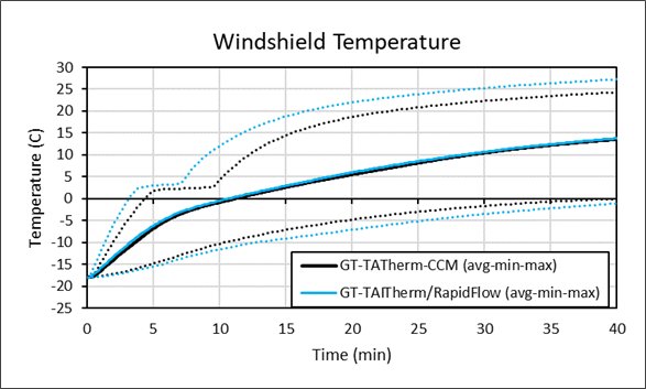
Results show generally good agreement in percent melted area between the two methods, with the GT-TAITherm-RapidFlow solution (blue line) closely tracking the higher-fidelity three-tool coupling (black line) for both Zone A and Zone B.

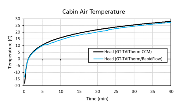
Windshield average interior surface temperatures also exhibit strong correlation, although larger discrepancies are observed in minimum and maximum temperatures, potentially indicating larger differences in local airflow distribution. Similarly, average head-level temperatures show reasonable agreement.
 |
 |
Ice thickness contours over time are comparable in the primary defrost region, with more significant deviations further from the main airflow.
 |
 |
While the GT-TAITherm-RapidFlow method may sacrifice some localized accuracy in air and surface temperature predictions and ice melting patterns compared to the full CFD coupling , it offers a significantly faster simulation time, enabling rapid design studies. This faster workflow allows for efficient exploration of various design parameters, including glazing properties, HVAC sizing, active heating technologies (like conductive transparent films), and ductwork/vent adjustments. Case studies demonstrate the ability to quickly assess the impact of these modifications on defrost performance, such as the limited effect of a low-emissivity coating, the benefits of increased glass conductivity or blower/heating capacity, and the significant potential of conductive transparent films for rapid defrost with lower energy consumption.

Conclusions
Simulation can be used to obtain accurate predictions of vehicle defrost performance. The GT-TAITherm/RapidFlow cabin workflow provides a favorable tradeoff between accuracy and computational time, enabling rapid design studies. TAITherm's visualization and reporting tools facilitate the analysis of defrost patterns, ice thickness, and percent area melted against performance targets. Future developments for RapidFlow include local mesh refinement for better resolution of HVAC ductwork and vents, and moisture transport modeling in the air for demist/defog applications, further enhancing the capabilities of this rapid simulation approach.
About the Author
 Deniz Hinz, PH.D. is a Senior Thermal and CFD Engineer at ThermoAnalytics Inc., where he leads the development and validation of advanced cabin simulation methodologies. Deniz specializes in coupling 1D and 3D solvers with human thermal comfort modeling to create integrated multiphysics simulation workflows for cabin environments. Recognized for his meticulous approach and innovative problem solving, he delivers solutions that are both highly accurate and tailored to client-specific needs. Deniz holds a BSE in Chemical Engineering from the University of Michigan and a PhD from the Illinois Institute of Technology, where his research centered on CFD model development and validation for complex, multiphase flows.
