This blog will explore how dynamic satellite simulation performed with MuSES™ and CoTherm™ can predict in-orbit transient temperatures and generate remotely sensed images in the electro-optic/infrared (EO/IR) spectrum. The space mission landscape has been dramatically altered in recent years, including the significant proliferation of small satellite launches. These small satellites, including CubeSats, feature small volumes packed with high-power components, reduced radiative surface areas, and other thermal control system limitations that make thermal management a challenging (but critical) task. Temperature oscillations induced by a satellite passing from sunlit to eclipsed orbit segments are exaggerated when thermal mass is relatively small, leading to undesirable temperature extremes for key components.
Keeping critical components (including battery cells) inside specified operational temperature limits can often be achieved with careful material choices and deliberate thermal control strategies. Hence, efficiently predicting dynamic in-orbit temperatures with high-fidelity simulation models is paramount to satellite design. With MuSES™ and CoTherm™, transient temperature prediction of orbiting satellites is now possible. Thermal-electrical solutions can be obtained by combining a 3D surface/volume mesh with appropriate thermal material properties, available using the included database and applying active heat sources. A battery management system can be included to control battery cell discharging (due to electrical loads) and charging based on battery charge status and the availability of harvested solar energy from photovoltaic (PV) panels.
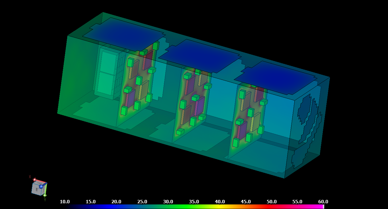
The example below illustrates temperatures simultaneously during a low earth orbit (LEO) transient simulation for external and internal components using partial transparency. Internal circuit boards and battery cell temperatures are visualized along with exterior solar panels. Many other results visualizations are possible, including absorbed solar flux and green/yellow/red indications for which components either fall outside their operating condition temperature range or are marginal.
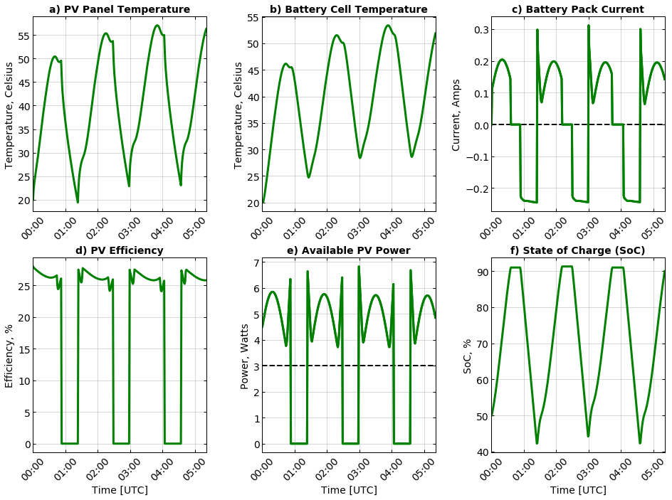
The six results panels below indicate some inter-dependent electrical and thermal performance results from this example LEO transient simulation, which spans several successive orbits. PV module temperatures (as well as solar incidence angle and degradation) impact solar-harvesting efficiency, influencing the available power for electronics and battery charging. Battery pack current depends on the need to supply power during eclipses and the ability to charge when excess sunlight can be stored. The battery state of charge (SoC) shows when the pack is fully charged, charging (during periods of excess sunlight) and discharging (in the absence of sufficient PV-supplied power). These thermal-electrical results illustrate the comprehensive approach and high-fidelity capabilities of MuSESTM in this domain. These are necessary for making sound design decisions and creating credible EO/IR models in the infrared spectrum, which depend heavily on accurate temperatures.
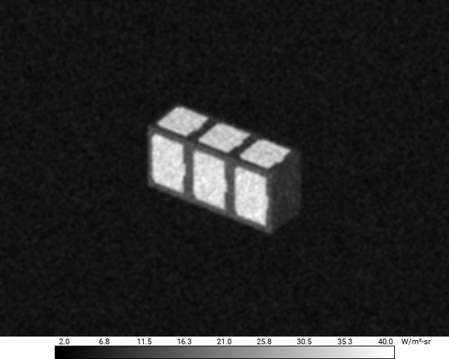
Additionally, predicting what an orbiting satellite would look like to a remote sensor may interest electro-optical/infrared (EO/IR) analysts. This might be to avoid collisions with unregistered satellites or space debris or perhaps even for defense-related observational purposes. Realistic EO/IR signature prediction (visible through LWIR wavebands, so 0.4-20 microns) of orbiting satellites is possible with MuSES™. Signature prediction in thermal infrared wavebands (e.g., MWIR and LWIR) depends primarily (but not exclusively) on temperature. At the same time, short-wave spectra (e.g., VIS and NIR, for example) are typically dominated by reflected solar energy. Wavelength-dependent optical surface properties for various external (and internal) surfaces are applied to the simulation model; radiance images are then generated from the perspective of a user-defined sensor, including emitted and diffuse/specular reflected energy. The rendered image below was generated for a single orbit time/position during the CubeSat’s LEO; blur and noise due to the optical sensor were included for demonstration purposes.
CoTherm™ provides automation capabilities for managing the simulation of dynamic orbiting satellites, including orbit propagation, temperature prediction, and EO/IR image generation. The CoTherm™ process can be designed to accept simple orbit parameters as input or employ one of several sophisticated orbit planning tools, perform transient thermal calculations, and even simulate what a virtual remote sensor would observe based on user-specified sensor platform parameters.
The satellite simulation strategy discussed here can incorporate the following important capabilities:
- Detailed 3D finite element geometry of satellites, including solar panels, battery cells, internal electronics, multi-layer insulation (MLI) blankets, thermal control strategies, etc.
- Application of thermal material properties, optical surface properties, internal heat sources, and transient orbital conditions for accurate dynamic mission-specific heat transfer calculations
- Ability to integrate the thermal and electrical battery simulations, as the thermal environment impacts battery electrical performance, and battery cell temperatures affect the thermal environment.
- Ability to consider the dependence of photovoltaic array performance on temperature changes, solar angle of incidence, and radiation degradation
- Inclusion of a battery management system that imparts the ability to realistically handle battery charge and discharge, based on available PV-harvested power and the presence of electronic loads
- Ability to specify detector waveband and resolution, sensor-target slant range, the optical field of view, sensor perspective, and other input parameters for sensor image generation
- Inclusion of optical sensor system effects, such as blurring and noise, representative of real-world measured images
- Ability to automate these capabilities in an efficient, documented process
We have discussed and demonstrated this process in more detail during a recent webinar (November 2023; see our support site) and several recent publications; please check out the links below and contact us for more information!
"Small Satellite Validation of a Simulation Approach for Assessing Dynamic Temperatures in Orbit" (ICES 2023) can be found at https://ttu-ir.tdl.org/handle/2346/94572
“High-Fidelity Simulation of Dynamic Thermal Satellite Signatures with MuSES” (AMOS, Sept. 2023) can be found at https://amostech.com/TechnicalPapers/2023/Poster/Demars.pdf
If you are interested in learning more about how the simulation capabilities of MuSES can help your team, please feel free to request a live demo of our software.
Visit our website at suppport.thermoanalytics.com for
- FAQs
- Webinars
- Tutorials
Get help from our technical support team:

Webinars:
Simulating the Thermal Impact of a High-Energy Laser on a Battery-Powered UAV with MuSES Webinar
High-Fidelity EO-IR Scene Simulation with MuSES and DIRSIG Webinar
Blogs:
MuSES + Human Thermal Extension
https://blog.thermoanalytics.com/blog/muses-human-thermal-module
EO/IR Services
https://blog.thermoanalytics.com/blog/thermoanalytics-eo-ir-services-overview
Plume Modeling
https://blog.thermoanalytics.com/blog/plume-modeling-muses
Camouflage Texture Mapping
https://blog.thermoanalytics.com/blog/camouflage-texture-mapping-muses
Webpages:
Software:
https://www.thermoanalytics.com/muses
Services:
EO/IR Image Sets
https://www.thermoanalytics.com/eo-ir-image-sets
Signature Management
https://www.thermoanalytics.com/signature-management
Video:
What is MuSES?
https://vimeo.com/manage/videos/457819919?embedded=true&source=video_title&owner=16056768

