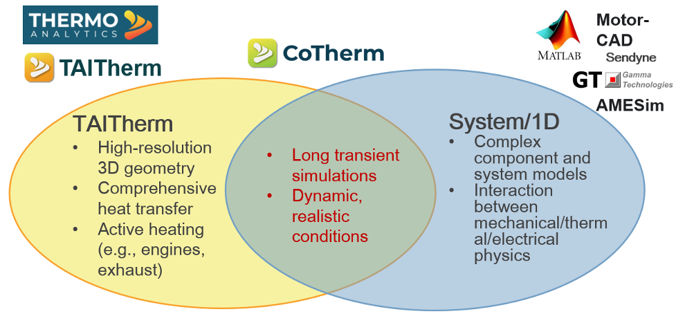
This blog will explore how to design better battery thermal and charger management systems using TAITherm and CoTherm with system modeling tools. There are many motivations for combining TAITherm and system/1D models: TAITherm provides high-resolution 3D geometry and comprehensive heat transfer; CoTherm covers long transient simulations and dynamic, realistic conditions; and System/1D models can be complex component and system models, as well as providing interaction between the mechanical, thermal, and electrical physics domains.
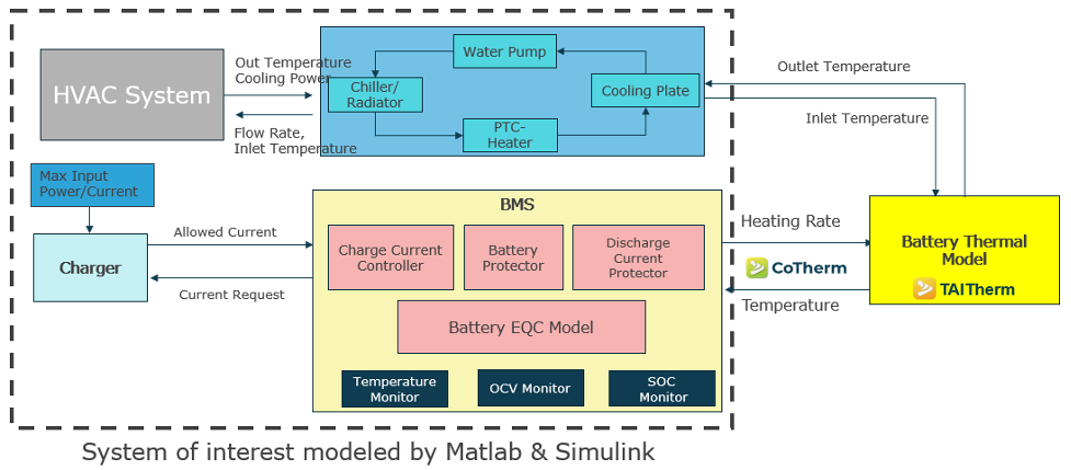
Excessive temperature rise during charge/discharge operations can cause capacity degradation, premature aging, and temperature-related stresses, so an easy-to-use process that allows parametric studies is critical to ensuring battery system performance and durability. ThermoAnalytics and EThermo Japan have developed a coupled process using TAITherm, CoTherm, and Matlab Simulink to evaluate battery temperature and electrical profiles during rapid charging. A schematic of the battery management system (BMS) modeling approach is shown below.
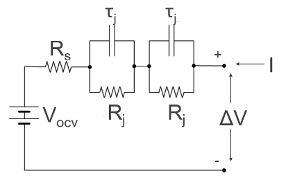
The battery cell model is fit to experimental data to capture the transient voltage response as a function of temperature, depth-of-discharge (DoD), charge/discharge, and current rate (C-Rate). For this study, the charge/discharge and C-Rate dependence was not used, but the model is available for the full 4D characterization. Two R-C pairs are used in this implementation of the NREL equivalent circuit model in Simulink.
The BMS/fast charger model contains the battery pack and the BMS/Charging control circuits. The coupled input parameters are the cell temperatures (from TAITherm), and the coupled output parameters are the cell heat rates, coolant flow rates, and coolant inlet temperatures. Other inputs are the maximum power, maximum current, maximum temperature, maximum charge time, and DoD cutoff. Other outputs include the power, current, voltage, and DoD of each cell.
For the parametric study shown here, only one module was used to evaluate the regulation of charge current based on cell temperature and thermal/electric management system design. The full pack is later used in a repeated charge/US06 drive cycle profile study.
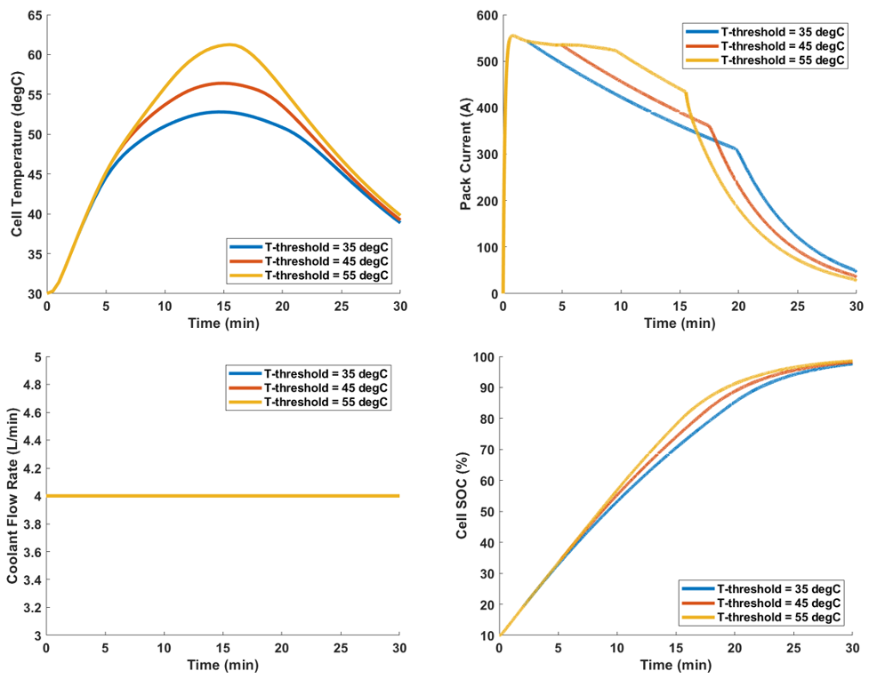
The first parametric study that was performed involved changing the maximum temperature limit of the cells. The results show that the maximum temperature of the cells responded to the temperature limits with some overshoot, so setting appropriate temperature limits may involve some calibration of the set points and/or time constants of the control circuit. When a high-temperature limit is used, the pack current stays close to the maximum for about half of the charge and then drops low due to the overshoot of the temperature and the thermal mass of the cells. When lower temperature limits are used, the current is reduced right away and then becomes higher as the current drop influences the heating in the cells.
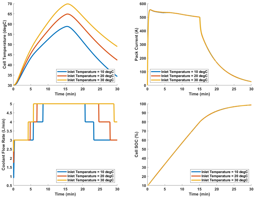
The second parametric study involved allowing the coolant flow rate to vary based on a 2D LUT for coolant flow rate as a function of battery temperature and state of charge. The LUTs for coolant flow rate and coolant inlet temperature are shown here. Due to the interdependence of the two control variables, they were considered independently but could be combined with a more sophisticated algorithm or a thermal model of the coolant heat exchanger system.

Controlling the coolant flow rate is a more efficient way of regulating cell temperature and does not result in a decrease in current to regulate the cell temperature. Three different inlet temperatures were considered for this study, and the figure below shows the coolant flow rate profile for the three cases. If inlet temperature is higher, then higher coolant flow rates are required to maintain cell temperatures.
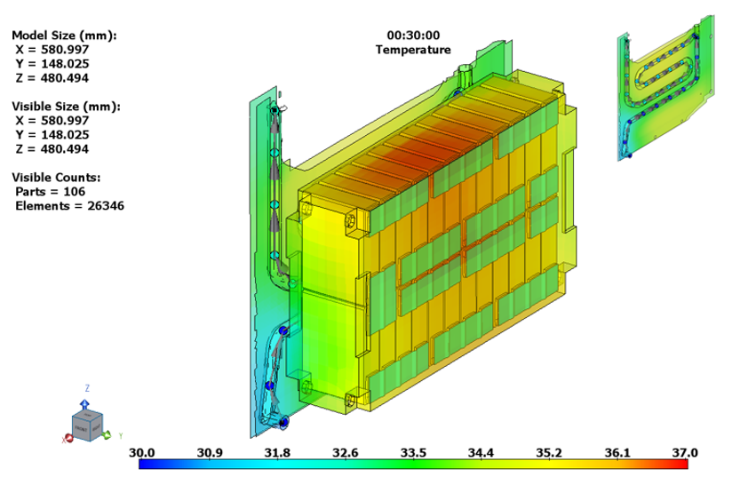
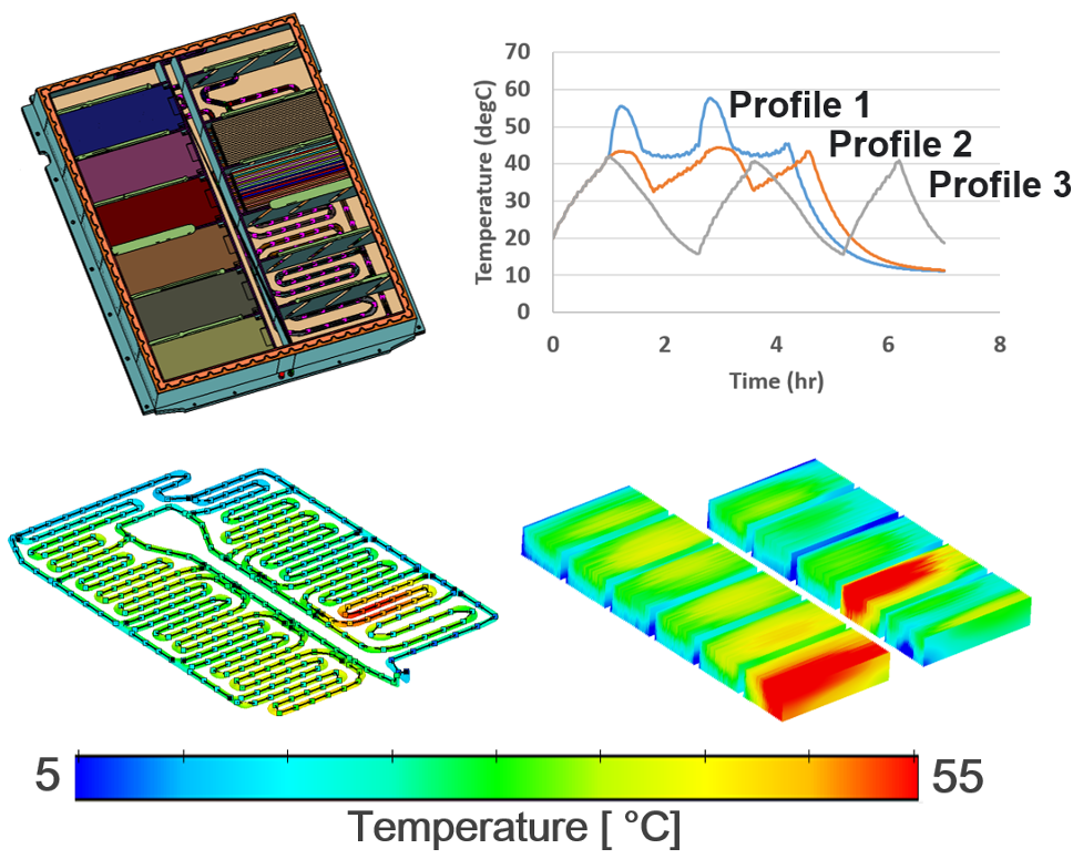
As a final case study, a full-scale battery pack was simulated to evaluate the distribution of temperatures throughout the pack and cold plate. The coolant inlet temperature and flow rate from Simulink were used to control a fluid stream network using library convection in TAITherm for the heat transfer coefficients. Results showed that for this design, there were significant temperature differences within the pack, mostly due to the location of the fluid streams with respect to the battery modules. After this first simulation step, it was determined that the cold plate flow network should be re-designed to correspond to cell locations in the battery pack.
In conclusion, carefully considering battery packaging, cooling, and operating environments can help you create a plan that meets requirements. CoTherm is a robust platform for coupling TAITherm 3D thermal models with 1D system tools. Modeling thermal management systems in TAITherm allows engineers to design durable, efficient, and high-performance products that will be competitive in the electrification marketplace. Both can provide the necessary insight to help you achieve your goals for a robust battery pack and control system design.
If you want to learn more about designing better battery thermal and charger management systems using TAITherm and CoTherm with system modeling tools, please feel free to request a live demo of our software.
Visit our website at suppport.thermoanalytics.com for
- FAQs
- Webinars
- Tutorials
Get help from our technical support team:

Watch our Designing EV Battery Fast Charging and Thermal Management Systems using TAITherm webinar as we demonstrate how comprehensive electrified vehicle simulation can be achieved using TAITherm and CoTherm with system modeling tools to design better battery thermal management and charger management systems.
TAIThermTM is a 3D thermal simulation software that predicts temperatures using transient or steady-state analysis. TAITherm thermal analysis software is as easy to use as it is powerful. It solves for solar and thermal radiation, convection, and conduction, including ever-changing environments. TAITherm removes the burden of complicated thermal simulations and ensures your design will function optimally in real-world scenarios.

